Injector driving

All about our superior engine management unit.
PBU
Posts:134
Joined:Mon Oct 27, 2014 12:42 am
Injector driving

Post by PBU » Sat Nov 22, 2014 8:34 pm

Some more from the fluke.

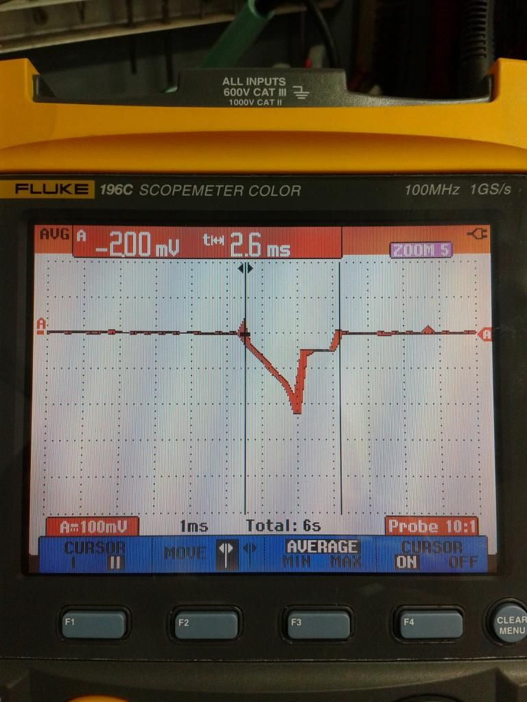
This is the original marelli injector current when driving the weber 025 injectors.They are low impedance.So i use a 4.7ohm resisitor on the ecumaster injector output.
Image

You can see the opening and hold current. ( 100mV = 1A )

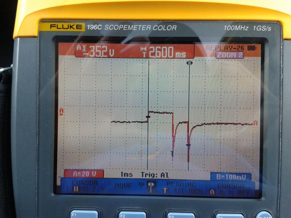
This is tension with the marelli ecu.

Image


On the ecumaster current is different. Didn't measure tension.
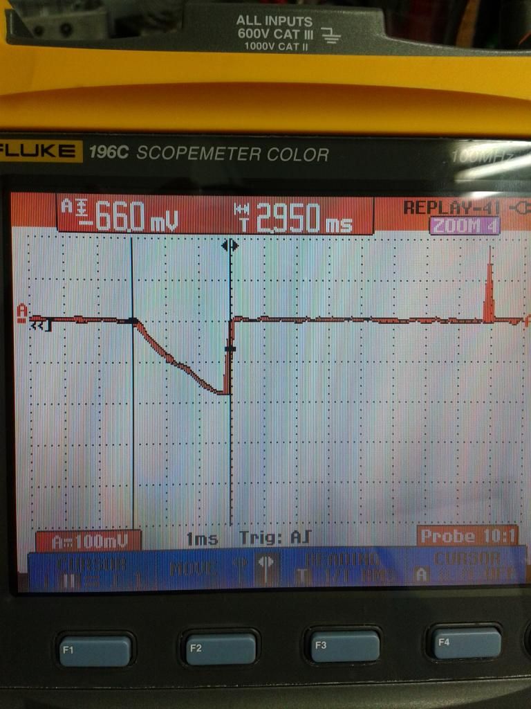
Image

There is no opening and hold current and the max current is also lower. 1.8Amp in stead of 2.2Amp.
Can i select open and hold driving on the ecumaster or is this not an issue ?
Is the injector driving fast enough to get good control.

Grts
Patrick
User avatar
Jadzwin
Site Admin
Posts:1445
Joined:Tue Aug 12, 2014 11:27 pm

Re: Injector driving

Post by Jadzwin » Sat Nov 22, 2014 9:37 pm

This is not an issue. For saturated injectors the control looks like on the last scope.

BTW: Very nice scopometer!

PBU
Posts:134
Joined:Mon Oct 27, 2014 12:42 am

Re: Injector driving

Post by PBU » Sat Nov 22, 2014 10:12 pm

Jadzwin wrote:BTW: Very nice scopometer!
Yes indeed. Been playing with it all day long on the engine .
Happy like a little kid. :P

Sadly i have to give it back. :(


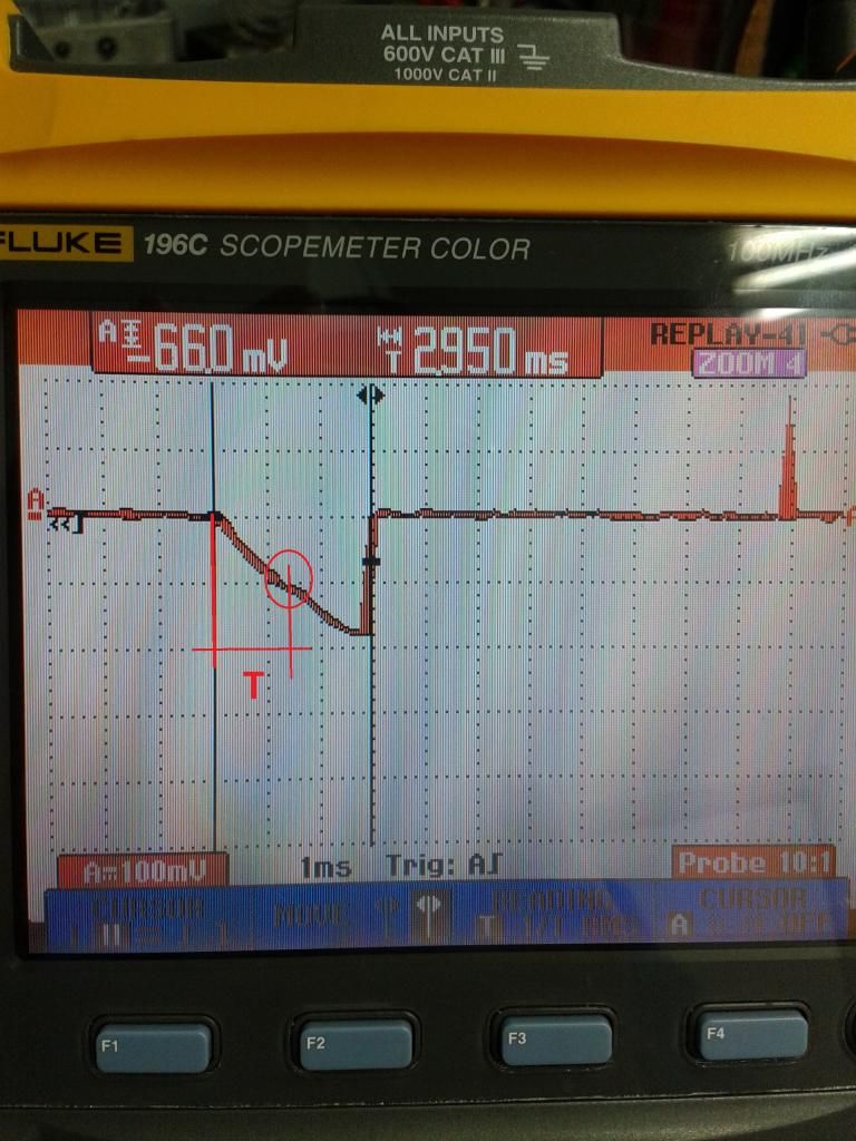
In the circle you see the little bump.
This is the effective opening off the injector.
So "T" is that the dead time or latency ?
I my case +- 1.3 msec.

Image

PBU
Posts:134
Joined:Mon Oct 27, 2014 12:42 am

Re: Injector driving

Post by PBU » Sat Jan 03, 2015 9:29 pm

Hi

Made a first test with my arduino programmable injector tester.
This way i can test the flow and latency of my injectors..

I can program exact number of pulses end PW.


http://youtu.be/-eTVm8MFXkc

Grts
Patrick ;)

PBU
Posts:134
Joined:Mon Oct 27, 2014 12:42 am

Re: Injector driving

Post by PBU » Sun Jan 04, 2015 9:00 pm

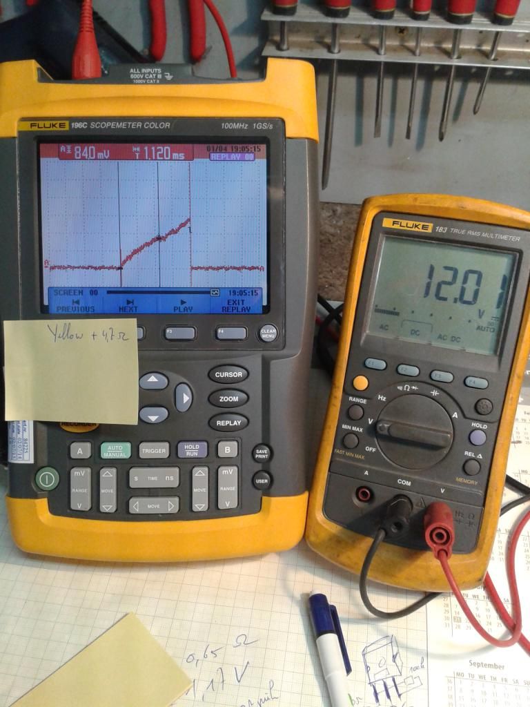
Tested the original 311 cc yellow cosworth injector + ballast resisitor of 4.7 ohm today.
For the moment whitout fuel. Going to do that in the next days.
You can see the latency of 1.12 msec but whitout fuel. Wonder if the fuel pressure will change a lot the latency.

Also changed the switching transistor to a very fast power mosfet. IRFP460 very fast, strong (20A) and very low RDS on.
Special for swicthing inductive loads.


Image

User avatar
Jadzwin
Site Admin
Posts:1445
Joined:Tue Aug 12, 2014 11:27 pm

Re: Injector driving

Post by Jadzwin » Mon Jan 05, 2015 1:43 pm

You can try 3R3 resistor

You should use internal EMU transistor. There are very good protected and selected to work with injectors.
EMU FETS have 0.1Ohm rds on in comparison to 0.27Ohm of IRFP460. In aspects of speed the time of turning on is measured in ns what does not influence injectors work.

In my opinion fuel pressure will add at least 0.2-0.3 ms to the latency time.

PBU
Posts:134
Joined:Mon Oct 27, 2014 12:42 am

Re: Injector driving

Post by PBU » Mon Jan 05, 2015 6:22 pm

Jadzwin wrote:You can try 3R3 resistor

You should use internal EMU transistor. There are very good protected and selected to work with injectors.
EMU FETS have 0.1Ohm rds on in comparison to 0.27Ohm of IRFP460. In aspects of speed the time of turning on is measured in ns what does not influence injectors work.

In my opinion fuel pressure will add at least 0.2-0.3 ms to the latency time.

Haha , you checked the IRPF460. Exactly 0.27 ohm RDS on. :D

Or course in the car i use the internal fets.
The IRPF i had laying around. Perfekt for testing.
Now make something for adding fuel . :|

User avatar
Jadzwin
Site Admin
Posts:1445
Joined:Tue Aug 12, 2014 11:27 pm

Re: Injector driving

Post by Jadzwin » Mon Jan 05, 2015 6:28 pm

yes i've checked :)

I like your approach :)

PBU
Posts:134
Joined:Mon Oct 27, 2014 12:42 am

Re: Injector driving

Post by PBU » Mon Jan 05, 2015 9:36 pm

Jadzwin wrote:yes i've checked :)

I like your approach :)
8-) If you ever have a job i come work for ECUmaster.

User avatar
Jadzwin
Site Admin
Posts:1445
Joined:Tue Aug 12, 2014 11:27 pm

Re: Injector driving

Post by Jadzwin » Mon Jan 05, 2015 9:59 pm

I will remeber :)

PBU
Posts:134
Joined:Mon Oct 27, 2014 12:42 am

Re: Injector driving

Post by PBU » Tue Jan 06, 2015 10:12 pm

Read something interesting today.

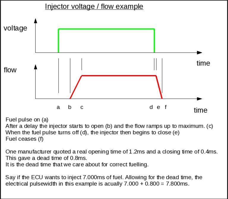
They said the dead time = opening time ( what i was talking about till now and visble on scope images above ) - closing time ( not looked at till now ).
So what do we fill in the injector adj table ? Opening time or the dead time calculated as above ?
Difference in msec is big !!.


Grts
Patrick

PBU
Posts:134
Joined:Mon Oct 27, 2014 12:42 am

Re: Injector driving

Post by PBU » Wed Jan 07, 2015 8:25 pm

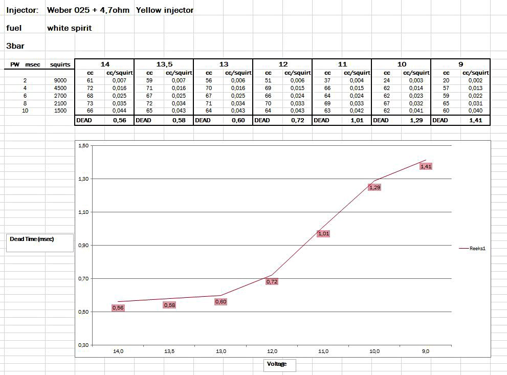
Tested the weber 025 injector today.

http://youtu.be/66QZ4JVlgyI


Here the result :

Image


Next the bosch 410cc injectors

;)

User avatar
Jadzwin
Site Admin
Posts:1445
Joined:Tue Aug 12, 2014 11:27 pm

Re: Injector driving

Post by Jadzwin » Wed Jan 07, 2015 8:42 pm

Looks very good and resonable.
Could you make the same test with 3R3 resistor ?

As I understand the method you use, both times (open and close) are considered.

PBU
Posts:134
Joined:Mon Oct 27, 2014 12:42 am

Re: Injector driving

Post by PBU » Wed Jan 07, 2015 9:05 pm

Jadzwin wrote:Looks very good and resonable.
Could you make the same test with 3R3 resistor ?

As I understand the method you use, both times (open and close) are considered.
Indeed. But this a mathematical calculation !
The slope/curve of the injected fuel/msec on a chart is continued . Where it crosses the horizontal axis at that point is the dead time. This method should be very precise.
Opening + closing time is considered.
You can find info on google about this calculation.
I will send you the xls by mail.


I think a 3R3 resistor i not a very good idea.
As with longer opening times the injector coil is completly saturated and current is reaching 2 amps.
Is this not the max continues current ?
Many times i even see a 6R8 resistor being used.

I will make a very carefull ( fire !! ) test outside with petrol this weekend to check if the diffirence between white spirit ( very close to petrol on what i found ) and petrol is big.
Maybe i can scale the the results according to different flow.

PBU

PBU
Posts:134
Joined:Mon Oct 27, 2014 12:42 am

Re: Injector driving

Post by PBU » Thu Jan 08, 2015 6:10 pm

Here is a good explenation.
As this is very important for making a good fuel map , please post your opinions.

Image


Grts
Patrick

User avatar
clem
Posts:83
Joined:Tue Nov 18, 2014 2:46 pm

Re: Injector driving

Post by clem » Fri Jan 09, 2015 4:00 pm

As I run a little injector cleaning workshop, I am very curious about that thread. I used your picture PBU and modified it:
Inj deadtime.png
What time is measurable with the oszilloscope? As I get it, it is the length AB. Are there other times measurable with oszilloscope only?
on this webpage http://injector-rehab.com/shop/lag.html is an other approach to this theme.

The times BC, CE and EF could be measured with a very fast pressure sensor, like piezo sensors used for engine indication. When the injector starts to lift its needle, a pressure drop occures (B). At point C the pressure stabilizes at a certain value. When the needle begins so close the valve (E) the pressure will rise due to the dynamic energy in the moving fuel. At point F the pressure begins to sink down to the static pressure. Combined with the measurements of the oszilloscope precise measurements of these times would be possible! BUT ... the required budget for such equipment is wayyyy too high for me as a student :(
Inj deadtime lab.jpg
kind regards Clem
Fuel Injector cleaning and flow measuring service needed? -> contact me :)

User avatar
Jadzwin
Site Admin
Posts:1445
Joined:Tue Aug 12, 2014 11:27 pm

Re: Injector driving

Post by Jadzwin » Fri Jan 09, 2015 5:56 pm

PBU approach is more statistically. He measures the injector flow at different pulse width and he is able to calculate dead time.
Good point is that he start from 2ms, for shorter times the injector could be very nonlinear.

PBU
Posts:134
Joined:Mon Oct 27, 2014 12:42 am

Re: Injector driving

Post by PBU » Fri Jan 09, 2015 8:45 pm

Jadzwin wrote:PBU approach is more statistically. He measures the injector flow at different pulse width and he is able to calculate dead time.
Good point is that he start from 2ms, for shorter times the injector could be very nonlinear.

The non linear area should be avoided. There is no garanteed ,equal, fuel amount injected.
This is why the sierra cosworth RS500 ( very rare and expensive cosworth !! ) has 2 injectors per cylinder.
The second one comes in at mid range - high boost revs.

Maybe an idea for ECUmaster but no easy to DIY construct on an engine. :?

Tomorrow i am going to test my current 0280150402 400cc bosch injectors.

PS
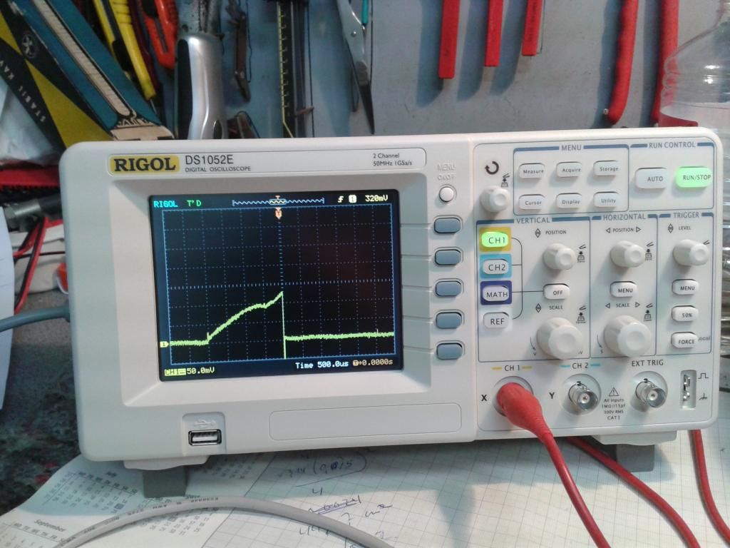
Here is my new toy :-)
Not as good as the fluke , correct , but for 300 euro unbeatable !!!
Image
Last edited by PBU on Sun Jan 11, 2015 2:48 pm, edited 2 times in total.

User avatar
Jadzwin
Site Admin
Posts:1445
Joined:Tue Aug 12, 2014 11:27 pm

Re: Injector driving

Post by Jadzwin » Fri Jan 09, 2015 10:28 pm

We use RIGOL scope and logi analyzers and this hardware is very ok. For that price you will not buy better scope

PBU
Posts:134
Joined:Mon Oct 27, 2014 12:42 am

Re: Injector driving

Post by PBU » Sat Jan 10, 2015 5:25 pm

Hi

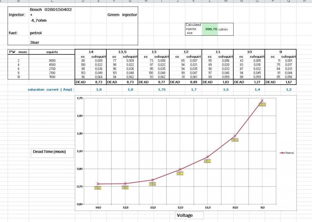
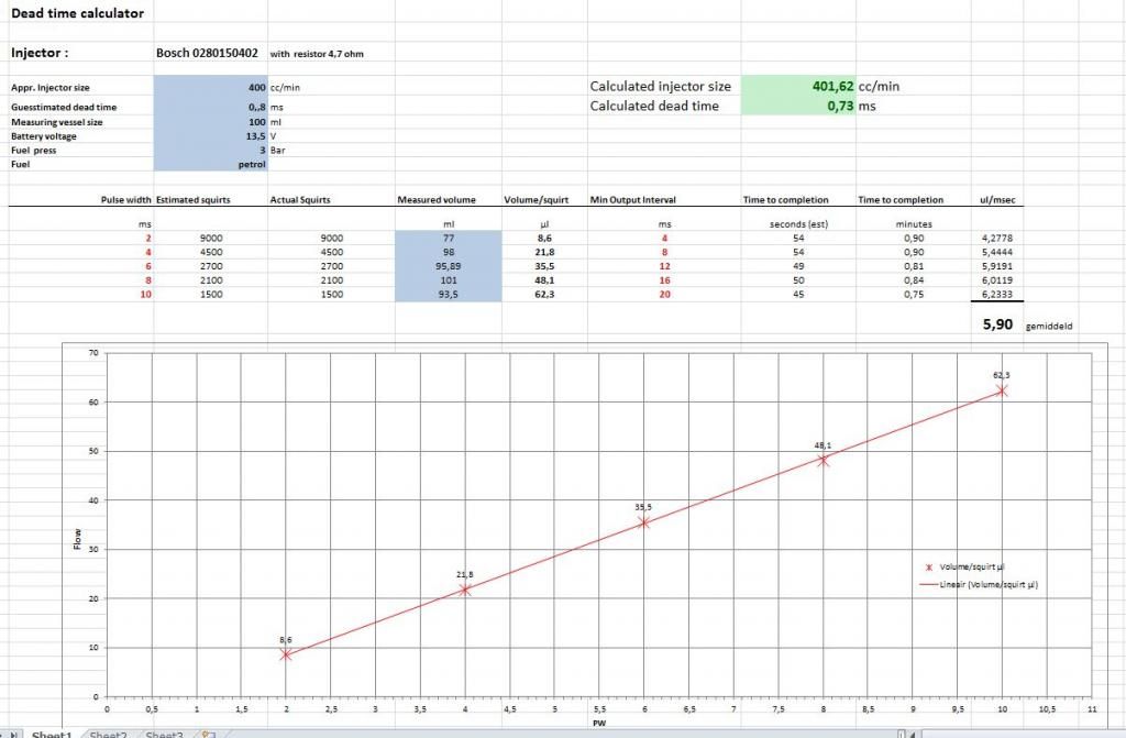
Tested the bosch 0280150402 today with white spirit and petrol.
This is tested with 4.7ohm resistor in series. !

You have both graphs results with petrol.

The difference between the flow test with white spirit and petrol was exactly 1.115- 1.12 more fuel flow with petrol.
You can see on the second graph the injector is niceley linear on 13.5V .
On 2 msec PW this injector should not be used below 11V . Very unstable results !!
You can also see the calculated injector size . Exactly what the Bosch specs told.

Image

Image


When using these graphs , please mention my name. :-) Put a lot of effort in it.


Grts
Patrick Bulcke
Antwerp Belgium
Last edited by PBU on Sun Jan 11, 2015 11:24 am, edited 2 times in total.

Locked