Hey guys,
Just received my EMU earlier this week and I am in the middle of making a harness for the car with the flying led harness from ECU masters. I have some initial questions i would like to get clarified before i go too deep into the wiring. I have spent a good amount of time searching for some of these questions as well as reading the manual. hopefully these will be simple questions for you experienced guys. Motor is a 2JZ GTE VVTI aristo motor from japan, and it will be going into a S13 240sx.
wiring clarification: VVTI related
primary trigger to crank sensor (VR = shielded)
Camsync ln 1 to camshaft position sensor (also shielded)
AUX to camshaft timing sensor (to control VVTI)
Is the above correct?
Wiring clarification: sensor grounds
Since there is only one sensor ground on the EMU I am assuming it is okay to run all sensor grounds through one wire back to the EMU, shielded as well as non shielded. I am actually going to be using a mill-spec connector to go through my firewall, so i plan on using a shielded wire from the EMU up to the mil-spec and then branching off from the shielded wire for the other sensors that dont require shielding while still going through shielded for the ones that do. I will be grounding the shielding at the EMU side in the sensor ground (B18). With the shielding running through a mill spec connector I am assuming i should be okay connecting the shielding and the ground into the same pin on the female side of the connector and then connecting it back to the shielding from the male side after the connector. I will not be grounding the other side of the shielding as i heard this can create eddy currents or something of the sort.
I know this is a long post i just wanted to cover all my questions in one post.
Thanks in advance!
-Kyle
Wiring input please
Re: Wiring input please
Yes mostly correct.
The cam VVT position actuator is not a sensor but a solenoid valve working on a pwm signal, as such it should be wired with 12v power to one side and the other to EMU AUX output, Also it should have a DIODE across it, stripe to the +12v side, can be connected anywhere along the circuit.
All the sensors connect to the sensor ground that is correct incl the cam and crank position, shouldnt matter where or how they join together. Actual shields should be connected to the chassis ground at one end only, NOT the sensor ground.
Re: Wiring input please
RHD,
Thank you for the quick reply and clarification on the sensor ground shielding being through the chassis ground!
So for my application i will NOT use the camssync ln #2 for anything as i am only trying to control one cam, correct? Im trying to figure this out so i can get my wiring started. Ill describe what ill be using for my AUXs and analogs so that maybe someone can chime in if they think im missing something more important:
AUXs:
1-Radiator fans
2-Quick Spool valve
3-Boost controller
4-Fuel Relay
5-Main relay
6-VVTI
Analogs:
1-Map
2-Oil Pressure
3-Fuel Pressure
4-Mux switch (launch control, ALS, Rolling anti-lag)
Let me know what you guys think, I appreciate the opinions!
- Kyle
Re: Wiring input please
An you need some output for RPM output send to your Instrument Cluster
you can use also stepper outputs, if you dont use stepper for idle control
you can use also stepper outputs, if you dont use stepper for idle control
Re: Wiring input please
okay, heres the updated list of outputs and inputs:
AUX1 Boost Controller
AUX2 Quick Spool Valve
AUX3 VVTI PWM
AUX4 Tach
AUX5 Fuel Pump
AUX6 Main Relay
Analog1 Map
Analog2 Oil Pressure
Analog3 Fuel Pressure
Analog4 MUX Switch
Stepper 1A Fans
Stepper 2A Speedo
Stepper 1B Check Engine Light
Stepper 2B Shift Light
I do plan on mostly using a tablet for gauges but incase i forgot it or it breaks i should be able to have speedo and tach at least.
Thanks,
Kyle
Edit: or should I use the VVTI PWM with a stepper motor output since it has a built in flyback diode to simplify the wiring?
Re: Wiring input please
Stepper outputs are lower current so connect what need more current to AUX and what does not need so much on Stepper output. So everything what goes trough Relay can be switched by stepper output easy. Its recommended that every solenoid using PWM should be conected trough diode to prevent backvoltage flow.2J-240 wrote:okay, heres the updated list of outputs and inputs:
Edit: or should I use the VVTI PWM with a stepper motor output since it has a built in flyback diode to simplify the wiring?
Re: Wiring input please
Thank you! Ill stick to what i have listed. I do have a question, Is there a specific type of flyback diode that i need to purchase or will any one work?
Re: Wiring input please
Some generic type like 1N4002 nothing special, must be fast, and must handle some current.

Re: Wiring input please
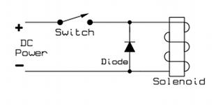
I dont know what ist better, but i am using connection of diode like that

Re: Wiring input please
That particular diode seems to be a 1A diode, is that big enough or should I look for something slightly larger? I was assuming 1 amp might not be enough.
-Kyle
Edit: Nvm, I will just use the flyback diode included in the box lol I just saw it.
-Kyle
Edit: Nvm, I will just use the flyback diode included in the box lol I just saw it.

Re: Wiring input please
You can connect Vtec (on/off type) directly to EMU without diode.
Re: Wiring input please
This is a VVTI motor, which if i am understanding correctly isnt a on/off type so it should need a diode, correct?
Re: Wiring input please
irrelevant question: why dont you use the internal MAP??
Any solenoid that operates on a relatively high PWM frequency should have a flyback diode
So in particular that is PWM idle valves (BMW etc) and all VVT cam solenoids.
Any solenoid has 2 wires, one is usually +12v and the other is the earth controlled by the EMU, and the diode just goes straight between the two wires with stripe to positive
Re: Wiring input please
RHD,
The reason for not using the onboard map is really just because of two reasons, 1 being that I already bought the sensor and would like to use it, but the main reason is due to the fact of not running a line into the cabin from the engine; I will be using a mil spec connector so that when this motor is pulled if disconnects (electrically) with one mils spec and some ground and powers.
My question for you...
When using a 12V power that I will be getting from the EMU output for VVTI control, wouldn't I ground to chassis ground not sensor ground? I was under the assumption that only 5V outputs return to the sensor ground while 12 volts will be chassis ground? I could be wrong, later I will post the ground ill be using for what sensors for more clarification so that I do it right the first time.
Thank you!
Kyle
Re: Wiring input please
In almost all cases you wire up things that do any sort of work with constant power from the main relay or battery etc and the EMU only controls the earth to activate. So in this case your solenoid will have one wire connected to +12v (same as injectors and ignition coils etc.) and the other wire connected to your Aux O/P from EMU, then diod across the two wires as in the diagram above (ignore the switch thats just a generic picture from the internet)
all the sensors have their own complete and separate regulated circuit with supply and earth thats why there is a separate sensor ground and should only be used for sesnors. They are kept separate to reduce any interference from all other circuits that are generally carrying much heavier currents.
all the sensors have their own complete and separate regulated circuit with supply and earth thats why there is a separate sensor ground and should only be used for sesnors. They are kept separate to reduce any interference from all other circuits that are generally carrying much heavier currents.